


Safe design of diverging junctions: crash cushions, barrier terminals and gore nose protection
During the holiday getaway period, traffic increases at junctions and access roads that many drivers are unfamiliar with. A late instruction from a satnav, an exit spotted at the last moment or a sudden reduction in speed can lead to abrupt changes in direction.
These manoeuvres are particularly critical at diverging junctions, where the main carriageway separates from an exit slip road. This creates a triangular area, commonly known as the gore, with a nose at which barriers, parapets, changes in level and other rigid features may converge.
Protecting this area requires more than simply extending the barriers along both routes. The design must assess possible approach paths, the available space, traffic speeds and how the different vehicle restraint systems connect to one another.
Why is a diverging junction a particularly sensitive location?
On a conventional road, the main route is usually clearly defined. At a diverging junction, drivers must interpret the signs, choose a route and adjust their position within a limited space.
When this decision is made too late, it can result in:
- Sudden braking before the slip road.
- Abrupt lane changes.
- Vehicles entering the hatched area.
- Impacts with the leading end of a barrier.
- Head-on collisions with the nose of the gore.
- Loss of control between the main carriageway and the exit.
The technical challenge arises when the barriers protecting both routes converge at a single point. Although these systems are designed to contain lateral impacts, the end of a barrier or parapet is not necessarily designed to withstand a head-on collision.
The solution must protect this point without introducing a new rigid obstacle into the vehicle’s likely path.
A conventional barrier cannot protect the nose of a diverging junction
Safety barriers and parapets are longitudinal systems. Their performance is primarily assessed for vehicles striking them laterally, which must be contained and redirected towards the carriageway.
At a diverging junction, however, a vehicle may approach head-on or at an angle very different from that envisaged for the longitudinal section. Directly joining the barriers along the two routes can therefore leave a highly rigid point exposed to traffic.
Crash cushions are specifically designed to protect obstacles that may be struck head-on. Their deformable structure progressively absorbs part of the collision energy and reduces the deceleration transmitted to the occupants.
They are commonly used at:
- The noses of forks and diverging junctions.
- The leading ends of central reserves.
- Structural piers.
- Toll plaza approaches.
- The leading ends of rigid parapets.
- Obstacles that cannot be removed or relocated.
Crash cushion or barrier terminal?
Crash cushions and terminals may look similar, but they do not perform exactly the same function.
A barrier terminal provides an appropriate end treatment for a longitudinal system. It connects to the end of a barrier or parapet and is intended to prevent that end from presenting a hazard to vehicles approaching head-on or from the side.
A crash cushion, by contrast, is positioned in front of an obstacle or a particularly hazardous arrangement. It does more than terminate a barrier: it acts as a separate device with a substantial capacity for deformation.
The choice between the two must be based on the actual site layout. At a straightforward diverging junction, where the barriers are sufficiently separated and set back, suitable terminals may be considered. Where the barriers converge or there is a rigid obstacle at the nose, a crash cushion may be required.
Metalesa explores this distinction in greater detail in its article on the criteria for using crash cushions and terminals.

Factors influencing the choice
There is no universal solution for every diverging junction. The design must consider several factors together.
Speed and performance level
Crash cushions are classified according to the speed used in their impact tests. The range may include performance levels 50, 80, 100 and 110, corresponding to the test conditions established for each device.
Selection must take account of the road speed and the path that an out-of-control vehicle could follow. On high-speed roads, both the impact energy and the distance required to absorb it will be greater.
Obstacle width
The device must cover the feature it is intended to protect. The narrow end of a barrier does not require the same configuration as two converging parapets or a wide central reserve.
Metalesa’s range includes crash cushions with different widths and performance levels, allowing the system to be adapted to different road layouts.
Deformation space
A crash cushion needs space to deform during an impact. Its position must prevent interference with obstacles behind it, changes in level, foundations or other features that could prevent it from functioning as intended.
The lateral space required and any potential encroachment into traffic lanes or hard shoulders during deformation must also be assessed.
Approach paths
A vehicle may reach the system from the main carriageway, from the exit slip road or after partially entering the hatched area.
It is therefore insufficient to assess only a fully head-on impact. The orientation, width and position of the device must account for the different foreseeable approach directions.
Connections to the barriers
When a device is integrated between longitudinal systems, continuity at the connections is essential. A poorly designed connection can introduce abrupt changes in stiffness, snagging points or unprotected areas.
The design must check compatibility with the barriers along both routes and ensure that no ends, posts or rigid components remain exposed.
Positioning within the hatched area
One of the most complex considerations is deciding where the device should begin within the diverging junction.
Installing it too close to the nose can leave part of the barriers exposed to a head-on impact. Positioning it too far upstream can occupy an area that could otherwise be traversed or bring it too close to the traffic lanes.
It is also necessary to determine which hard shoulder takes priority: the one alongside the main carriageway, the one alongside the exit slip road or a compromise between the two.
The Spanish Circular Order 35/2014 includes references to the use of crash cushions and terminals at diverging junctions. However, Metalesa notes that some aspects of positioning and selection are not addressed in the same detail as the criteria applicable to barriers and parapets. These include occupation of the hatched area, clearance from hard shoulders and the choice between one or several devices.
Each site therefore requires an individual assessment, coordinating the geometric design with the performance of the selected system.
The importance of full-scale testing
Crash cushions are assessed in accordance with UNE-EN 1317-3. The tests cover different speeds, directions and approach angles to assess their energy absorption capacity and the vehicle’s behaviour during the collision.
The performance characteristics assessed include:
- Impact severity for the occupants.
- Lateral displacement of the device.
- Redirection capability.
- The vehicle’s path after the collision.
- Longitudinal deformation of the system.
For example, Metalesa’s C110 models are tested to performance level 110 and carry CE marking in accordance with the applicable requirements.
These characteristics must be considered alongside the actual project conditions, as the outcome depends on both the product and its positioning, installation and connections to the surrounding equipment.

Installation, inspection and replacement
Once the system has been selected, installation must follow the assessed configuration, including foundations, anchorages, orientation, height, components and distances from the barriers.
After an impact, the device must be inspected to determine which parts require replacement. The connections, anchorages and nearby longitudinal systems must also be checked.
At access roads with high seasonal traffic volumes, maintenance before peak travel periods provides an opportunity to check that the crash cushion retains its geometry, that no components are deformed and that its operating area remains clear of obstacles.
Providing protection when a driver makes a late decision
At a diverging junction, a wrong decision can turn a normal vehicle path into a head-on collision within seconds. Advance signing and a clear road layout help prevent this situation, but passive safety measures must be ready to act once an error has occurred.
Terminals provide safe end treatments for barriers. Crash cushions protect noses, obstacles and layouts that may be struck head-on. Connections and transitions ensure that the overall system maintains the necessary continuity.
Metalesa designs and supplies road equipment to address these layouts, with a range of crash cushions, terminals and vehicle restraint systems suited to different speeds, widths and geometries.
On access roads to tourist destinations, increased traffic makes the risk more apparent. However, the need to protect diverging junctions correctly remains throughout the year: a safe junction must be designed to prevent a late decision from becoming a collision with irreversible consequences.


The new framework for intelligent transport systems in Spain
Road digitalisation involves more than installing sensors, cameras or illuminated signs. For these technologies to work in a coordinated way, the different systems must be able to exchange data, use compatible formats and communicate information to public authorities, operators and users.
Royal Decree 450/2026, published on 5 June, establishes a new framework for deploying Intelligent Transport Systems in Spain. The legislation transposes European Directive 2023/2661 into national law and replaces Royal Decree 662/2012, which had regulated this field for more than a decade.
Although the legislation uses the Spanish abbreviation SIT, the English abbreviation ITS, standing for Intelligent Transport Systems, is also widely used in the sector.
What does Royal Decree 450/2026 regulate?
The new royal decree does not prescribe a single technological solution or require the deployment of a specific application. Its purpose is to establish the general conditions for the coordinated and consistent deployment of ITS in road transport and its interfaces with other modes of transport.
The legislation defines Intelligent Transport Systems as systems that apply information and communication technologies to:
- Road infrastructure.
- Vehicles.
- Road users.
- Traffic and mobility management.
- Interfaces between road transport and other modes of transport.
The framework covers a wide range of applications: traffic information, incident management, multimodal mobility, cooperative systems, weather data, connected vehicle operation and the communication of restrictions and road hazards.
Smart junctions can therefore form part of the ITS ecosystem, but they are just one of many possible applications.
Data at the heart of connected mobility
One of the key elements of Royal Decree 450/2026 is data availability, access and exchange.
A connected road can generate information about traffic conditions, weather, roadworks, restrictions, accidents, obstacles and the availability of certain services. However, these data are only useful at network level when they can be shared in a structured way.
The legislation establishes obligations relating to data availability and the provision of certain ITS services. It also updates the General Traffic Regulations to strengthen the real-time communication of limitations, restrictions, incidents and events affecting traffic.
This affects public bodies as well as infrastructure managers, operators and providers that generate or use mobility-related information.
National access points
The royal decree establishes different National Access Points as digital nodes that facilitate access to data from multiple sources.
These include:
- The National Access Point for Traffic and Mobility.
- The National Access Point for Multimodal Transport.
- The National Access Point for Safe and Secure Parking Areas for Trucks and Commercial Vehicles.
Spain’s Directorate-General for Traffic must publish the requirements for exchanging and communicating data to the National Access Point for Traffic and Mobility within a maximum of twenty-four months of the royal decree entering into force.
These nodes enable information generated by different public authorities and operators to be used in management platforms, navigation services, control centres and connected vehicles.
Interoperability: beyond installing sensors
Equipping infrastructure with sensors makes it possible to detect events, but does not in itself guarantee that the information reaches those who need to use it.
To form part of an ITS environment, devices must be integrated into an architecture capable of:
- Collecting data from different sources.
- Sharing information using compatible formats.
- Communicating with external platforms.
- Triggering responses to specific events.
- Maintaining service continuity across geographical areas and operators.
The royal decree defines interoperability as the ability of systems and their processes to exchange data, share information and enable the continuity of ITS services.
Progress towards connected mobility therefore involves more than adding isolated technologies: it requires the deployment of equipment designed to communicate within a wider network.
Cooperative systems: C-ITS
The new framework includes Cooperative Intelligent Transport Systems, or C-ITS, among its priority areas.
These systems enable information exchange between vehicles, infrastructure and other users. An incident detected on the road can be communicated to a control centre, the emergency services, a navigation application or directly to a connected vehicle.
The aim is to ensure that information does not remain solely at the location where it was generated, but can be used to manage traffic and warn other users.
Solutions such as PlugSmart® Pro turn existing equipment into connected devices. The system can detect different risk scenarios and communicate events to regional or national access points, management centres and mobility-related services.
Road equipment within digital infrastructure
Roads feature barriers, parapets, terminals, crash cushions and other devices traditionally designed to perform a physical function. Adding sensors, connectivity and signalling gives these elements new capabilities.
A connected vehicle restraint system can detect an impact, identify adverse conditions or activate an illuminated warning. The information can then be transmitted to a management platform to support monitoring and intervention.
PLUG&META® technology enables these functions to be integrated into different urban and interurban environments. Its application turns road equipment into a node capable of detecting, signalling and communicating hazardous situations.
In urban environments, Metaurban® SMART combines vehicle containment, lighting and sensing to generate real-time information and trigger responses relating to pedestrians, speed, visibility or road incidents.
Does the royal decree provide a definitive boost?
Royal Decree 450/2026 does not, in itself, mean that new devices will be installed immediately on every road. Nor does it specify a particular technology for each situation.
Its main contribution is to update the legal framework, expand the priority areas and strengthen obligations relating to data, services and interoperability. Specific technical requirements will need to be developed through European legislation, ministerial orders and subsequent resolutions.
It is therefore more accurate to describe it as an update and consolidation of the framework for Intelligent Transport Systems than as a definitive boost to a particular application.
Infrastructure designed to share information
The new regulatory landscape places interoperability and data availability at the heart of transport digitalisation.
Public authorities and infrastructure managers will need to consider not only which devices to install, but also how they will connect, what information they will generate, which platforms they will be able to communicate with and how they will integrate into national and European services.
Metalesa develops connected and intelligent equipment designed to combine physical safety, risk detection, signalling and communication with external systems.
The evolution of roads depends on integrating these capabilities into equipment from the design stage, so that each element can fulfil its protective function while also participating in a connected mobility network.

New regulations for road digitalisation and safety
During June 2026, two royal decrees were approved concerning traffic management, road digitalisation and the protection of vulnerable road users.
The first is Royal Decree 450/2026 of 3 June, which establishes the framework for deploying intelligent transport systems in Spain. The second is Royal Decree 518/2026 of 24 June, which amends the General Traffic Regulations concerning the protection of vulnerable road users.
The two pieces of legislation regulate different areas. Royal Decree 450/2026 focuses on data, interoperability and digital transport services. Royal Decree 518/2026 amends traffic rules affecting pedestrians, cyclists, motorcyclists and users of personal mobility vehicles, among other groups.
1. Royal Decree 450/2026 on Intelligent Transport Systems
Royal Decree 450/2026 establishes the framework for the coordinated deployment and use of Intelligent Transport Systems, referred to by the Spanish abbreviation SIT in the legislation.
Its scope covers road transport and its interfaces with other modes of transport. The decree transposes Directive (EU) 2023/2661 into Spanish law and replaces Royal Decree 662/2012, which had regulated this area since 2012.
Intelligent Transport Systems apply information and communication technologies to infrastructure, vehicles, users, and traffic and mobility management.
The decree identifies four priority areas:
- Information and mobility services.
- Traffic and transport management services.
- Applications relating to road safety.
- Cooperative intelligent transport systems.
The latter, also known as C-ITS and referred to as SIT-C in the Spanish legislation, enable information exchange between vehicles, between vehicles and infrastructure, or between different components of the infrastructure itself.
2. Availability and exchange of traffic data
One of the central elements of Royal Decree 450/2026 is the availability of road and mobility data.
The decree establishes obligations concerning certain data and services within specific geographical areas. The information covered includes data on infrastructure, traffic rules, restrictions, network conditions, incidents, traffic and the availability of certain mobility services.
The royal decree also regulates national access points as digital interfaces for accessing data from different authorities and operators.
Three main nodes are envisaged:
- The National Access Point for Traffic and Mobility.
- The National Access Point for Multimodal Transport.
- The National Access Point for Safe and Secure Parking Areas for Trucks and Commercial Vehicles.
Within a maximum of twenty-four months of the royal decree entering into force, Spain’s Directorate-General for Traffic must publish a resolution setting out the requirements for exchanging and communicating data to the National Access Point for Traffic and Mobility.
3. Digitalisation of road equipment
ITS applications may include sensors, communication systems, management platforms and devices installed on the infrastructure.
The use of sensors makes it possible to collect information on physical quantities, traffic, environmental conditions, the presence of road users or impacts against particular elements. The data can be sent to platforms or control centres for processing.
In the field of road equipment, Metalesa develops vehicle restraint systems and ITS equipment for high-capacity roads that combine physical protection with monitoring and communication technologies.
PlugSmart® Pro technology enables digital functions to be added to vehicle restraint systems. Meanwhile, Metaurban® SMART integrates sensors, LED lighting and connections to external traffic management systems.
These solutions can measure variables such as temperature, proximity, acceleration and ambient light levels, as well as activate light signals and transmit information to control centres.

4. Royal Decree 518/2026 on vulnerable road users
Royal Decree 518/2026 amends the General Traffic Regulations and other provisions relating to the movement of pedestrians, cyclists, motorcyclists and personal mobility vehicles.
The decree introduces the definition of a vulnerable road user or a road user at greater risk of vulnerability. This refers to anyone who, because of their mode of travel or the physical characteristics of their age group, faces a greater risk of injury or of more severe injuries in the event of an accident.
It also updates concepts such as cycle route, cycle lane, protected cycle lane, cycle track on a pavement, shared-level street, residential priority zone and safe route to school.
The amendments concerning motorcycles include permission to use the hard shoulder in certain congested traffic conditions, compulsory protective gloves on interurban roads, the use of closed footwear and the requirement to carry a high-visibility reflective vest. The royal decree will enter into force on 1 October 2026.
The amendments relate to the design and management of spaces shared by different modes of travel. In infrastructure terms, these spaces may incorporate motorcyclist protection systems, cyclist-pedestrian railings, physical separators, parapets and signalling devices.
5. Two areas of regulation relating to the road network
Royal Decree 450/2026 regulates the coordinated deployment of technologies, data and digital services for road transport. Royal Decree 518/2026 updates traffic rules relating to vulnerable road user safety and urban mobility.
The first concerns the collection, availability and exchange of traffic and mobility information. The second introduces changes to road user behaviour, road-related definitions and traffic conditions.
Together, the two provisions form part of the regulations approved in 2026 concerning traffic management, the digitalisation of road infrastructure and the regulation of different road users.
Summer driving risks and how infrastructure should respond
Summer changes the usual driving conditions. Long-distance journeys, traffic in tourist areas and overnight travel intended to avoid the hottest hours all increase. At the same time, high temperatures can increase fatigue, reduce concentration and place greater mechanical demands on vehicles.
This combination of factors reduces the time available to react to pedestrians, congestion, bends, obstacles or unexpected changes in road conditions. Summer road safety therefore depends not only on the driver and vehicle maintenance. Infrastructure must also help detect risks, provide timely warnings and reduce the consequences of a potential accident.
Heat, fatigue and reduced reaction capability
High temperatures can cause tiredness, drowsiness and irritability, particularly during long journeys. When a driver spends several hours at the wheel, their ability to remain attentive and react to an unexpected event may be reduced.
Heat also affects the vehicle. Tyres operate at higher temperatures, and any existing problem involving pressure, wear, overloading or deterioration can increase the risk of a puncture or structural failure.
An apparently manageable situation, such as congestion beyond a bend or a pedestrian beginning to cross, can therefore become a serious danger when reduced attention, high speed and insufficient braking distance occur together.
Driving at night during the summer
During the summer months, night-time journeys associated with leisure activities, holidays and travel back from tourist areas become more frequent. However, driving at night reduces the distance at which certain hazards can be identified.
Pedestrians, cyclists, stationary vehicles and obstacles outside the main beam of the headlights may be detected too late. This is particularly relevant on roads passing through towns and villages, approaches to populated areas, leisure districts and pedestrian crossings with limited lighting.
Conventional signs may not be sufficient at these locations. A fixed sign always conveys the same message, regardless of whether an immediate hazard is present. Adaptive road lighting and intelligent signs, by contrast, can improve visibility and activate a warning when a risk is actually present.
ITS for a dynamic response
Intelligent Transport Systems, commonly known as ITS, combine sensors, communications, lighting and signalling devices to detect what is happening on the road and respond in real time.
Their main advantage is that they turn infrastructure into an active element. Instead of simply displaying a permanent sign, the system can recognise a specific situation and generate an appropriate warning.
Possible applications include:
- Detecting pedestrians at critical crossings.
- Enhancing bend warning signs at night.
- Warning drivers about excessive speed.
- Providing warnings about congestion or stationary vehicles.
- Activating lighting in conditions of poor visibility.
- Detecting impacts against restraint systems.
- Collecting traffic and mobility information.
Devices such as PlugSmart® Pro can turn a conventional restraint system into an intelligent element capable of detecting risks and generating warnings from the infrastructure itself.
These solutions are particularly useful during the summer, when traffic volumes and travel patterns vary according to the time of day, the day of the week or tourism activity.
Dynamic LED road studs at pedestrian crossings
Collisions involving pedestrians on roads through populated areas and in urban environments can be reduced through dynamic LED road stud systems. When a sensor detects that someone is approaching a pedestrian crossing, it can activate a light signal directed towards approaching drivers.
The purpose is to improve the visibility of the crossing point and attract attention at the precise moment when a risk is present.
This system can:
- Improve the night-time visibility of the crossing.
- Warn drivers that pedestrians are actually present.
- Prevent drivers from becoming accustomed to a permanently active signal.
- Adapt its operation to specific schedules or conditions.
- Record data about the use of the crossing.
Metalesa’s Metaurban® SMART parapet can integrate sensors and LED lights to generate warnings on the carriageway. Its applications include pedestrian detection, excessive speed warnings, lighting for pedestrian and cycle routes, and alerts in the event of fog, congestion or impacts.
The restraint system therefore ceases to be an exclusively passive element and becomes part of connected infrastructure.
Risk of tyre failures involving heavy vehicles
High temperatures can aggravate tyre maintenance problems. In a heavy vehicle, a sudden failure can cause a loss of control that is difficult to correct because of the vehicle’s considerable mass and the energy generated while it is moving.
The risk increases when an incident occurs on a motorway, bridge or viaduct. At these locations, a vehicle leaving the carriageway can have particularly serious consequences.
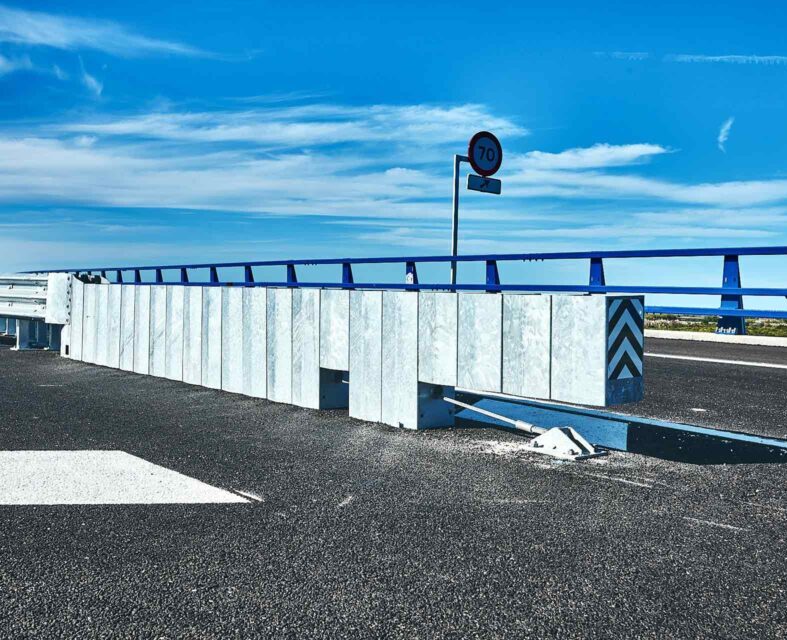
Infrastructure should therefore incorporate steel bridge parapets with a containment level appropriate for the expected traffic. These systems are designed to contain and redirect vehicles, reducing the possibility of them passing beyond the edge of the structure.
Metalesa’s META16 steel bridge parapet has an H3 containment level and is intended to protect areas carrying vehicles with a high mass. One example of its application is the installation of three kilometres of META16 on the A-23 viaducts.
The effectiveness of these systems also depends on correct installation, the strength of the anchors and the appropriate treatment of transitions and terminals.
Active and passive safety
The response to summer driving risks must combine two levels of protection.
ITS, sensors and LED devices act before an accident occurs. Their role is to detect a dangerous situation, improve the information available and give the driver more time to react.
Parapets and restraint systems act when an accident can no longer be prevented. Their purpose is to contain the vehicle and reduce the consequences of leaving the carriageway or losing control.
Both strategies must work together:
- Active safety anticipates the risk.
- Passive safety limits the severity of the impact.
- Connectivity enables data to be collected.
- Maintenance preserves the performance of the system.
Infrastructure prepared for summer
Summer mobility combines heavier traffic, high temperatures, fatigue and increased night-time travel. In this scenario, infrastructure must be capable of adapting to actual road conditions.
ITS and dynamic LED road studs can reinforce warnings during periods of increased risk. High-containment parapets, meanwhile, provide a final layer of protection in accidents involving heavy vehicles on motorways, bridges and viaducts.
Metalesa develops solutions that integrate active and passive safety by combining restraint systems, sensors, lighting and intelligent signalling.
The objective is to move towards roads that can detect danger, warn users and reduce the consequences when an accident cannot be prevented.
Challenges and solutions in the design of vehicle restraint systems for cyclists and motorcyclists
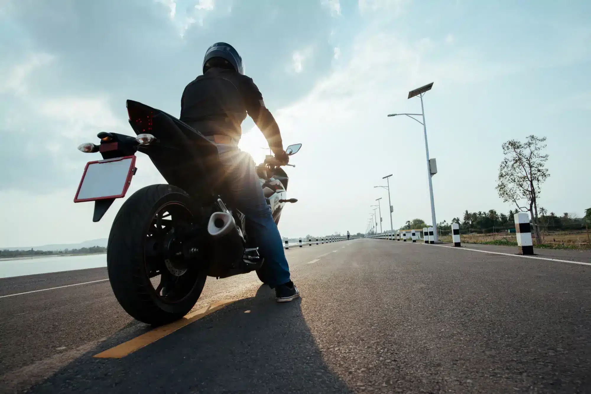
Motorcyclists are among the most vulnerable road users. Unlike the occupants of a car, they do not have a protective structure capable of absorbing impact energy. As a result, a fall or run-off-road collision can have particularly serious consequences.
The studies on motorcycle collisions on interurban roads published by Forenvision analyse accidents recorded between 2017 and 2024. They pay particular attention to run-off-road collisions, one of the most severe types of accident involving motorcycle users.
The figures illustrate the scale of the problem. In 2024, 478 motorcycle or moped users were killed in Spain, accounting for 26.8% of all road traffic fatalities. Spain also has more than 4.3 million registered motorcycles.
This situation makes it necessary to design roads that not only seek to prevent accidents, but also reduce their consequences when they occur.
1. Run-off-road collisions: a particularly dangerous scenario
A vehicle may leave the road for many different reasons, including inappropriate speed, loss of grip, distraction, evasive manoeuvres, the condition of the road surface or complex road geometry.
For motorcyclists, the dynamics of a collision are usually different from those involving four-wheeled vehicles. After losing control, a rider may fall onto the carriageway and slide until they strike a safety barrier or another object located on the roadside.
Conventional steel safety barriers are designed to contain and redirect vehicles. However, their posts can become highly dangerous impact points for someone sliding along the ground. This risk is commonly known as the guillotine effect because of the high concentration of forces that may be exerted on the body.
Vehicle restraint engineering must therefore consider not only the behaviour of the vehicle, but also the possible interaction between the motorcyclist and the infrastructure. In this context, road restraint systems must be selected according to the type of road, its speed, the road users present and the foreseeable consequences of a vehicle leaving the carriageway.
2. What are Motorcycle Protection Systems?
Motorcycle Protection Systems, commonly known as MPS, are devices normally installed along the lower section of steel safety barriers.
Their purpose is to close the gap between the barrier and the ground, cover the posts and create a continuous longitudinal surface. This helps prevent direct impacts against rigid components and reduces the severity of injuries.
A properly designed MPS can:
- Prevent direct contact between the motorcyclist and the barrier posts.
- Reduce the presence of exposed edges and sharp surfaces.
- Distribute the impact across a larger surface.
- Guide the rider’s body along the system.
- Prevent the rider from passing underneath the barrier.
Metalesa has developed the Metaurban® steel parapet with a Motorcycle Protection System, a solution that combines vehicle containment with specific protection for road users who may slide along the carriageway after falling.
The application of these solutions is also discussed in the article Parapets also protect motorcyclists, which examines the need to incorporate systems adapted to this vulnerable group.
3. Where should MPS be installed?
The installation of Motorcycle Protection Systems should be based on a specific risk assessment. Not every section of road has the same characteristics or presents the same potential consequences.
Installation is particularly important in the following locations:
- Tight bends or sections with pronounced changes in alignment.
- Sections with a history of motorcycle collisions.
- Secondary roads frequently used by motorcyclists.
- Areas with changes in level, embankments or rigid obstacles.
- Interchanges, slip roads, merging lanes and exits.
- Sections where a loss of control could lead directly towards a barrier.
Secondary roads require particular attention because they often combine successive bends, narrow hard strips or verges, accesses, junctions and roadside objects close to the carriageway. These roads are also frequently used by motorcyclists, particularly at weekends and during leisure periods.
4. Continuity, terminals and transitions
The effectiveness of a restraint system does not depend solely on the central section of the barrier. Its ends, connections and transitions can also become critical points.
Barrier end terminals must prevent the beginning or end of the system from becoming a rigid obstacle during an impact. These devices are designed for installation at the ends of safety barriers and absorb part of the energy generated in a collision.
Similarly, transitions between restraint systems connect barriers or parapets from different product families or with different containment levels while maintaining an appropriate change in stiffness.
Projects intended to improve motorcyclist safety should assess the following elements together:
- The main safety barrier.
- The Motorcycle Protection System.
- The approach and departure terminals.
- The transitions between different systems.
- Roadside obstacles and changes in level.
- The space available for the system to deform.
A partial or incorrectly installed system may simply transfer the risk from one point to another. Protection must therefore remain continuous throughout the entire potential impact area.
The importance of addressing these points correctly is also discussed in the article about changes to the regulations governing safety barrier transitions and terminals.
5. Design, installation and maintenance
The performance of an MPS also depends on whether it is installed in accordance with the manufacturer’s specifications. Changes to its height, anchors, post spacing or connections may alter the response of the complete system during a collision.
Subsequent maintenance is equally important. Impacts, corrosion, unsuitable repairs or changes in ground level can reduce the effectiveness of the system.
Inspections should assess the condition of the rails, posts, bolts, anchors, terminals and transitions. They should also identify deformation, incompatible components or accumulations of soil and vegetation that could affect the device’s effective height.
6. Roads that are more forgiving of human error
Analysis of motorcycle collisions makes it possible to identify risk patterns and apply more effective measures. In run-off-road collisions, Motorcycle Protection Systems play an essential role in reducing the consequences of an impact against a steel safety barrier.
The objective is not simply to prevent the vehicle from leaving the carriageway. The infrastructure must also be prepared to protect the motorcyclist after a fall and prevent the restraint system itself from making the resulting injuries more severe.
At Metalesa, we design and manufacture road restraint systems adapted to the characteristics of each road. The use of MPS, safe terminals and properly designed transitions contributes to more forgiving roads that can reduce the severity of an accident when human error cannot be prevented.
Sustainability in infrastructure: Current standards and critical materials
Infrastructure management has evolved from being a matter of balancing functionality and cost to becoming an exercise in technical precision driven by mandatory environmental compliance. Today, the viability of a project is also inevitably measured by its ability to comply with a regulatory and financial framework that already requires quantifiable environmental sustainability as an immediate implementation requirement.
In today’s market, compliance with road safety standards is only the first step. The EU Taxonomy Regulation and the guidelines of the European Green Deal operate as binding technical regulations that determine the eligibility of suppliers within the sector. For manufacturers of metal infrastructure equipment, this translates into an operational obligation: full traceability. Products are no longer assessed solely on their physical durability, but also on their emissions balance, from raw material extraction through to the end of their life cycle.
This scenario has transformed sustainability into a fundamental technical specification. In high-level procurement processes, transparency in emissions data has become a decisive qualifying factor. The ability to certify environmental impact with scientific rigour is now the minimum level of technical capability required to operate within the industry.
1. Environmental Product Declaration (EPD)
Within the complex ecosystem of sustainable infrastructure, the Environmental Product Declaration (EPD) has become the definitive benchmark for transparency and the only "environmental passport" with recognised technical validity. While the market is often saturated with ambiguous green marketing claims (greenwashing), the EPD introduces a rigorous quantification methodology based on the international standards ISO 14025 and, specifically for the construction sector, EN 15804.
The relevance of the EPD for the specifier and the end client lies in three fundamental pillars:
- Scientific rigour and neutrality: Unlike a self-declaration, the EPD is not a value judgement on whether a product is "good" or "bad". It is a detailed inventory of environmental impacts based on objective data, verified by an independent third party. This external audit guarantees data integrity for public bodies and funding institutions.
- Objective comparability: The EPD standardises the Product Category Rules (PCR), allowing engineers, architects and specifiers to compare technical solutions from different manufacturers under the same functional unit and identical impact parameters. This turns sustainability into a variable as measurable and comparable as tensile strength or yield strength.
- Modular transparency: The document breaks down the impact into different stages, making it possible to identify at which point in the value chain the greatest footprint is generated. This granularity is essential for global impact calculations of large infrastructures, where the sum of individual EPDs for each component (barriers, posts, structures) forms the overall environmental profile of the works.
2. Life Cycle Assessment (LCA) as a central metric
The EPD is the final expression of an exhaustive Life Cycle Assessment (LCA) process. This analysis breaks down the environmental impact of the product across its entire continuous cycle, structured into standardised technical modules according to EN 15804, allowing a rigorous assessment from initial extraction through to reintegration into the circular economy:
2.1 Product stage
- Raw material supply (Module A1): Quantifies the impact of extraction, mining and initial processing of metals and basic resources.
- Transport to manufacturing plant (Module A2): Measures the logistics footprint of inputs from their origin to processing and manufacturing facilities.
- Manufacturing (Module A3): Precisely assesses electricity consumption, gaseous fuels, water resources and waste management generated during the product manufacturing process.
2.2 Construction process stage
- Transport of the product to site (Module A4): Records the logistical impact of transporting finished structures and equipment from the manufacturing plant to the final infrastructure project location.
- Installation and assembly process (Module A5): Includes energy consumption, machinery used, auxiliary materials and waste management generated during the installation and integration of the product into the works.
2.3 Use and Maintenance Stage
- Maintenance and repair (Modules B1 to B7): Assesses the impacts arising from the activities required to preserve the product’s technical performance throughout its service life. In the case of the steel–hot-dip galvanised combination, this module stands out for its minimal environmental footprint, as the metallurgical protection eliminates the need for repainting or periodic corrective maintenance, optimising the infrastructure’s environmental OPEX.
2.4 End-of-Life Stage
- Deconstruction and demolition (Module C1): Measures the resources and emissions associated with the dismantling and safe removal of the material once it has reached the end of its service life.
- Transport to waste management facilities (Module C2): Quantifies the logistics involved in transporting the removed material to treatment or recycling facilities.
- Processing and disposal (Modules C3 and C4): Analyses the final destination of the waste and the mechanical or thermal processes required for its separation and treatment.
2.5 Benefits and Loads Beyond the Life Cycle
- Recovery, recycling and reuse potential (Module D): This module lies at the heart of the circular economy. It quantifies the net environmental benefits provided by the product at the end of its service life by replacing the need to produce virgin raw materials. For steel structures, this value is exceptionally positive due to steel's inherent ability to be recycled indefinitely at a rate of 100% without losing any of its structural mechanical properties.
The LCA provides a multidimensional perspective that goes beyond the simple measurement of Global Warming Potential (GWP). It reports critical indicators such as soil and water acidification, depletion of abiotic resources and eutrophication, enabling comprehensive environmental risk management while providing transparent and easily auditable traceability for specifiers and public authorities.
Requirements for Green Public Procurement (GPP)
The rollout of Green Public Procurement has turned the manufacturer's EPD into a technical barrier to market entry. Public authorities no longer accept generic "industry average" data, instead requiring product-specific information that provides:
- Project accuracy: It enables designers and engineers to calculate the actual carbon footprint of a project by combining the precise data for each component, avoiding penalties resulting from environmental performance deviations.
- Supply assurance: It guarantees that the material delivered on site fully matches the certification submitted during the tendering process.
- Competitive advantage in European funding: In projects supported by NextGenerationEU funding, a manufacturer-specific EPD is often a technical qualification requirement that gives suppliers a competitive advantage over competitors competing solely on price.
3. The Steel–Hot-Dip Galvanising Combination
As the majority of the equipment manufactured by Metalesa is produced using steel and the hot-dip galvanising process, the following section examines how this material and manufacturing process contribute to the durability and circularity of these products, and consequently to the product's final EPD.
3.1 Steel in the Circular Economy
Steel is a permanent material that can be fully recovered and recycled without any degradation of its mechanical properties. The use of recycled steel can reduce CO2 emissions by up to 85% compared with primary steel production, supporting the sector's decarbonisation objectives.
3.2 Protection through Hot-Dip Galvanising (ISO 1461)
Durability is a technical requirement for preventing the premature depletion of resources. The hot-dip galvanising process, in accordance with UNE-EN ISO 1461, ensures long service life through:
- Metallurgical reaction: It creates zinc–iron alloy layers that are metallurgically bonded to the steel substrate, rather than forming a simple surface coating.
- OPEX optimisation: A galvanised structure eliminates the need for subsequent maintenance interventions, reducing operating costs and the environmental impact associated with repair works on site.
Ultimately, the implementation of EPDs and LCAs defines the current regulatory landscape of the market. The industry no longer operates on the premise that sustainability is an added value, but rather as a mandatory compliance protocol that is essential for the technical, commercial and legal viability of any infrastructure project.